

Solvent Recovery at Pharmaceutical and Chemical Production Plants
Comments Off on Solvent Recovery at Pharmaceutical and Chemical Production PlantsThe recovery and reuse of solvents used in the production processes at pharmaceutical, chemical, petrochemical, and medical device manufacturing facilities are an important consideration when evaluating a plant’s overall efficiency and profitability. Recovery and reuse of organic solvents offers a two-fold benefit: waste elimination costs and reduced chemical costs. Distillation is one of the most common methods used in a solvent recovery application.
Secondary to the recovery of solvents with distillation technology is the concentration/recovery of residual pharmaceutical product from the column discharge stream. Evaporation technology following the column is the standard method to facilitate higher recovery rates of the pharmaceutical product.
Simple Solvent Recovery
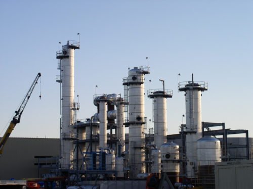
 The most basic design would typically have a single organic solvent in a water matrix with no contaminants present. Common chemicals in a solvent recovery process are acetone, isopropanol, methanol, ethanol, and hexane. A solvent recovery column has two sections of trays or packing. For example, with a water matrix and a chemical with a boiling point lower than water, the bottom section of the column (stripping section) would initially separate the water matrix and the organic chemical; the top section (rectification section) is used to concentrate the organic chemical. This binary system can typically be designed in common software simulation packages such as CHEMCAD and HYSYS.
Multicomponent Solvent Recovery
The next level system will have more than one organic chemical to recover. In this design, it is typical to recover the organic chemicals in one stream and water in the other. A second column is then used to separate the two organic solvents. Most of the common organic solvents have well-documented vapor/liquid equilibrium data required to properly simulate the separation process. Any small amount of contaminant should be cause for pilot testing of the design to ensure the separation requirements.
Additional Difficulties in Solvent Recovery Applications
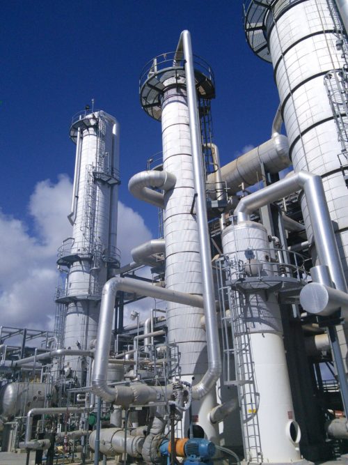 Many plants have several discrete production lines operating with different organic chemicals. It is possible to design a robust solvent recovery system that can operate in different configurations to facilitate the recovery of solvents from the various production lines. In one such case, a pharmaceutical production plant had varying streams of solvents in a matrix of water. The solvents had a range of boiling points that were above the BP of water from Line 1 and below the boiling point of water from Line 2. Adding to the complexity was the multicomponent nature of the streams from both lines. A third layer of complexity was the miscibility of some streams when rectified or concentrated and the immiscibility of other streams.
The design of the distillation system followed a standard path of initial simulation work, which would provide operating conditions within the column; liquid/vapor ratios, reflux ratios, utility requirements, etc. A test protocol for the different streams was then required due to the lack of empirical data to predict a distillation separation process with many components present. The column configuration included feed points at the top, middle, and bottom of the column. To account for the “immiscibility factor” a 3-section decanter design was used. In the presence of immiscible components, the three sections guaranteed separation of a stream with both a higher and lower specific gravity as compared to water. In the miscible component case, the decanter served as condensate tank for the overhead stream.
Final operating parameters were determined from the pilot test and a full-scale plant was built from the required empirical data.
Conclusion
Experienced distillation engineers draw upon their experiences in the design of each new system. The separation of solvents and water is only one half of the design. Since distillation is an energy-intensive process, the overall system design needs to take energy usage into great consideration. Using cascading pressure in a multi-effect distillation system can be used in some applications. Mechanical vapor recompression (MVR) can also be used to promote a more efficient system design. The overall economy of the process should be compared when evaluating designs from multiple suppliers of distillation equipment.
Thin Stillage Evaporation
Comments Off on Thin Stillage EvaporationWhat Is Thin Stillage?
Thin stillage evaporation concentrates a process stream consisting of water and dissolved solids. The process is most common in the ethanol industry, with the dissolved solids coming from the corn used to make ethanol. Undissolved solids typically have already been removed using a centrifuge. A stream that consists of both dissolved and undissolved solids is commonly known as whole stillage, a stream with just dissolved solids is thin stillage, while the concentrated thin stillage is referred to as syrup.
 A typical feed concentration to the evaporation system would be at 5% to 7%, while a typical final concentration from the evaporation system (the syrup) would have a concentration of 30% to 35%.
Where Is It Found?
The most common application for thin stillage evaporation is in ethanol plants, utilizing corn as a feedstock and producing fuel grade ethanol. The thin stillage evaporators allow the ethanol plant to concentrate up the dissolved solids, to either go to a dryer or sold as syrup. The dissolved solids come upstream from the fermentation process and consist of solids not digested in the ethanol fermenters. The dried solids (DDGS, Dried Distillers Grains with Solubles) can be sold to cattle farmers as feed, and has a long shelf life. Alternately, the syrup (CCDS, Corn Condensed Distillers Solubles) can be fed to cattle, however it has a much shorter life span.
How Is the Thin Stillage Concentrated?
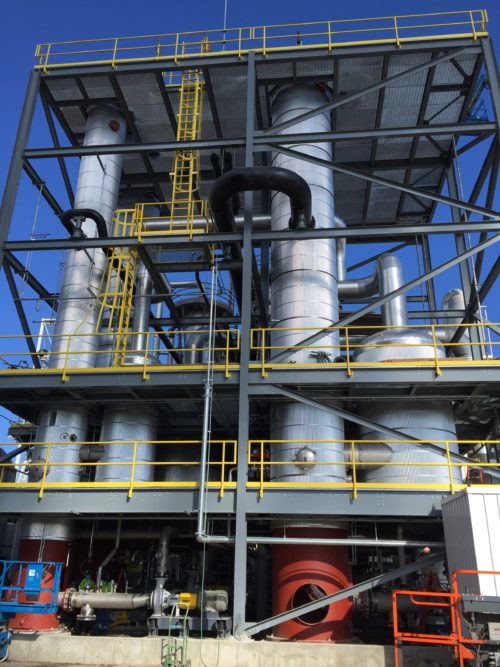
The thin stillage is concentrated by evaporating off the water, leaving a more concentrated stream. The process often requires multiple stages of evaporation and multiple effects to reduce the amount of heating media (steam) required.
Each time the process fluid is concentrated through evaporation, it’s considered one stage of evaporation. In a three stage evaporation system, for example, the thin stillage could be concentrated from 7% to 14%, then 14% to 30%, then finally 30% to 35%.
A multiple-effect evaporation system is a means by which we reduce utility steam consumption by utilizing the steam we generate in evaporation to evaporate the process stream in the next effect. We do this by reducing the pressure at which the evaporation takes place. As an example, the first stage evaporation may take place at 5.15 psia generating steam at 163.4F. The second effect would operate at 3.83 psia, where boiling would take place at 151.3F. The steam generated at 163.4F (produced using low-pressure steam available at the plant) would be utilized to generate the steam at 151.3 in the second effect. We could have a third effect as well, at a lower operating pressure and temperature.
Equipment Utilized
 Evaporation equipment utilized for this service typically consists of shell and tube heat exchangers, most often configured as falling film evaporators. Large diameter tubes are preferred as the thin stillage is fouling. As an alternate, plate and frame exchangers can also be utilized as suppressed boiling exchangers. Suppressed boiling occurs when the process steam has sufficient heat input into it in the liquid phase, as sensible heat under pressure, such that after exiting the exchanger it can be flashed. Suppressed boiling is utilized for plate and frame exchangers to reduce the potential for fouling of the plate and frame exchanger.
The Thermal Kinetics Advantage
Thermal Kinetics has extensive experience designing complete thin stillage evaporation systems. Our goal is to provide a system with the best payback period, balancing the cost of the utility steam versus the cost for a multiple-effect evaporation system. Thermal Kinetics also provides systems utilizing mechanical vapor recompression to further reduce utility steam consumption.
Our systems are typically run under vacuum where the operating temperature is low, reducing fouling rates and thereby increasing run times. Thermal Kinetics can supply the control valves, pumps, and all ancillary equipment (skidded system). Further, we recommend to our customers that they utilize a CIP system (clean in place) designed by Thermal Kinetics to clean the equipment with very minimal downtime.